La explicación
The Cartesian Plane and Coordinate Notation
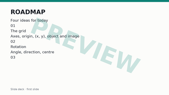
The Cartesian plane is a two-dimensional surface defined by a horizontal number line called the x-axis and a vertical number line called the y-axis. These two axes intersect at a right angle of 90 degrees at a point called the origin, denoted by the capital letter O with coordinates (0, 0). The plane is divided into four regions called quadrants, numbered in an anticlockwise direction starting from the top right as Quadrant 1, Quadrant 2, Quadrant 3, and Quadrant 4. Every point on the Cartesian plane is identified by an ordered pair of numbers written in the form (x, y). The first number is the x-coordinate, which measures the horizontal displacement from the y-axis, and the second number is the y-coordinate, which measures the vertical displacement from the x-axis. When a geometric shape undergoes a transformation, the original shape is referred to as the object, and the resulting shape is referred to as the image. Vertices of the object are typically labelled with capital letters such as A, B, and C, while the corresponding vertices of the image are labelled with prime notation such as A prime, B prime, and C prime, written as A', B', and C'.
Understanding Rotations and Their Properties
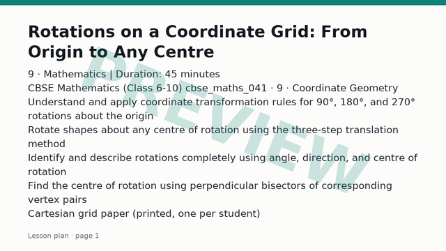
A rotation is a type of transformation that turns a shape about a fixed point called the centre of rotation. Every point on the shape moves along a circular path whose centre is this fixed point. To fully describe any rotation, three pieces of information must be specified: the angle of rotation, the direction of rotation, and the centre of rotation. The standard angles of rotation taught at this level are 90 degrees, 180 degrees, and 270 degrees. The direction can be either clockwise, which follows the forward motion of the hands of a clock, or anticlockwise, which is the opposite direction. A rotation of 270 degrees clockwise is equivalent in its final position to a rotation of 90 degrees anticlockwise, and a rotation of 270 degrees anticlockwise is equivalent to a rotation of 90 degrees clockwise. A rotation of 180 degrees results in the exact same final image regardless of whether it is performed in a clockwise or anticlockwise direction. Rotations are isometric transformations, meaning that the size, shape, area, and interior angles of the image are identical to those of the object. Only the orientation and position of the shape on the Cartesian plane change during a rotation.
Rotating Points about the Origin
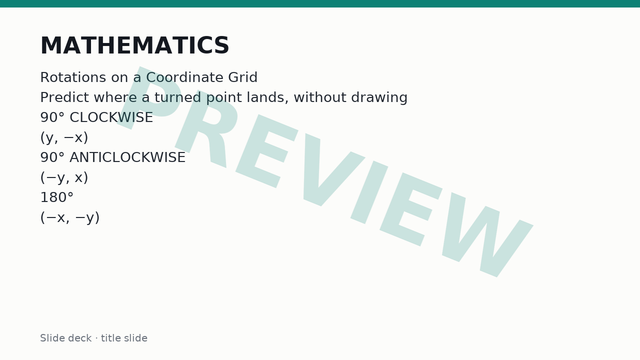
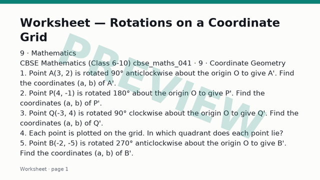
When the centre of rotation is the origin (0, 0), specific coordinate rules can be applied to find the coordinates of the image after standard rotations. For a 90 degrees clockwise rotation about the origin, a point with coordinates (x, y) maps to the new coordinates (y, negative x). For a 90 degrees anticlockwise rotation about the origin, a point with coordinates (x, y) maps to the new coordinates (negative y, x). For a 180 degrees rotation about the origin, the direction does not matter, and a point with coordinates (x, y) maps to the new coordinates (negative x, negative y). For a 270 degrees clockwise rotation about the origin, which is identical to a 90 degrees anticlockwise rotation, a point with coordinates (x, y) maps to the new coordinates (negative y, x). For a 270 degrees anticlockwise rotation about the origin, which is identical to a 90 degrees clockwise rotation, a point with coordinates (x, y) maps to the new coordinates (y, negative x). These rules provide a quick algebraic method for transforming individual vertices without needing to physically measure angles and distances with a protractor and ruler on the grid.
Rotating Shapes about Any Centre of Rotation
When the centre of rotation is a point other than the origin, such as the point (p, q), coordinate rules alone become complex, and a geometric method using tracing paper or coordinate vector translation is required. The systematic geometric method involves three steps. First, translate the entire coordinate system or shift the object so that the centre of rotation moves to the origin (0, 0). This is achieved by subtracting the coordinates of the centre of rotation from every vertex of the object, so that a vertex at (x, y) temporarily becomes (x minus p, y minus q). Second, apply the standard origin rotation rule corresponding to the required angle and direction to these adjusted coordinates. Third, translate the resulting coordinates back by adding the coordinates of the centre of rotation, yielding the final image coordinates. Alternatively, using tracing paper, a student draws the axes and the shape, places the point of a pencil or compass needle firmly on the centre of rotation, rotates the tracing paper by the specified angle and direction, and reads off the new coordinates where the vertices land on the underlying grid.
Describing Rotations Fully
To fully describe a single transformation that maps an object onto an image as a rotation, three distinct pieces of information must be stated in the final answer: the type of transformation, the angle and direction of rotation, and the coordinates of the centre of rotation. Omitting any one of these three elements makes the description incomplete. To find the centre of rotation when given an object and its image, a geometric construction method is used. Choose a pair of corresponding vertices, such as vertex A on the object and vertex A prime on the image. Draw a straight line connecting A to A prime, and construct the perpendicular bisector of this line segment. Repeat this process for a second pair of corresponding vertices, such as B and B prime, and construct the perpendicular bisector of the line segment connecting B to B prime. The exact point where these two perpendicular bisectors intersect on the Cartesian plane is the centre of rotation. The angle can then be measured using a protractor from the centre of rotation to vertex A and vertex A prime, and the direction is observed by noting whether the shape turned clockwise or anticlockwise.
Common Misconceptions and How to Avoid Them
Learners often encounter specific pitfalls when working with rotations on a coordinate grid. One frequent error is confusing the signs of coordinates when applying algebraic rules, such as writing (negative y, negative x) instead of (y, negative x) for a 90 degrees clockwise rotation. Another common mistake is assuming that the centre of rotation is always the origin (0, 0) even when a different point is explicitly stated in the problem. Students also sometimes confuse clockwise and anticlockwise directions, turning the shape to the left when a clockwise rotation was requested. A fourth error is attempting to rotate a shape by adding or subtracting values from the coordinates directly without accounting for the 90-degree angular sweep around the centre. Careful checking of individual vertex coordinates using tracing paper or by testing a single easy point, such as (1, 0), helps prevent these errors.